At RedRidge we’re always happy to talk to anyone about their project, and we do our estimates and proposals for free, which means we see a lot of different projects come through the door. Every few months we see a development project that’s stuck in the same unfortunate situation, the dead end prototype.
These meetings are always a little unpleasant for everyone, because the client usually thinks they’re very close to commercialization, but just needs a few small bugs fixed which are preventing the prototype from actually working, and then they’ll be ready to launch. In reality these are often prototypes which not only aren’t working, but don’t have a path forwards to a commercial product. Ultimately we have to break the bad news, and layout a real path to something commercializable, often with a lot of backtracking, which no one ever likes to hear.
In the software industry, most people are familiar with the idea of a dead-end codebase, which is built on such shaky foundations that it eventually becomes impossible to scale the system, and it needs to be thrown out in favor of a complete rewrite. This can be disastrous for a company, but because software engineers are acutely aware of this possibility, they tend to guard against it, and start examining their systems for scalability earlier in the design program. In the electronics design world, people are less guarded against this type of dead-end throw-away work outcome – but it still happens, particularly to entrepreneurs and inventors. The good thing is that these electronics designs are almost always extremely similar, and share a lot of the same issues, so they can be avoided from the outset if you know what to look for.
Most of these issues are already well known to experienced engineers and industry professional who are familiar with developing commercial electronic products, but we hope this can be a helpful primer for inventors, fresh engineering grads developing their first product, and entrepreneurs new to the hardware space. So, what makes a dead end prototype, and what are the warning signs?
Hobbyist Components
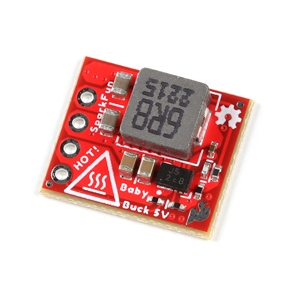
The advent of accessible development tools for embedded systems like Arduino, Raspberry Pi, Espressif ESP32, and python layers for embedded systems programming have made getting started on a proof of concept prototype easier than ever before. This is a great thing, and there’s nothing wrong with most of these platforms in and of themselves, but one has to be more careful with the world of breakout boards and sensor modules that have flourished around them. Modules from companies like Sparkfun, Adafruit, and DFRobot can get systems up and running with advanced functionality like WiFi connection or LiDAR range finding in a few hours. But not all these products are suitable for a design that will eventually be commercialized, and some of these modules can lead you into a dead-end prototype.
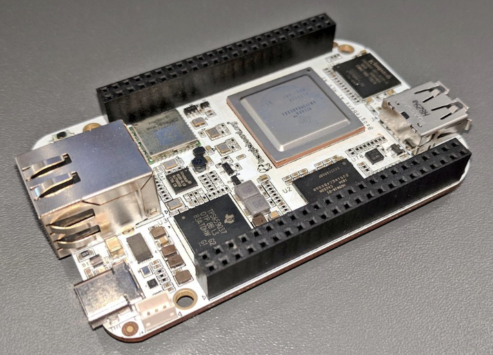
The important distinction is that there are 2 camps of these modules, the first are the true “breakout” boards. These are basically 3rd party development kits for one or more regular, industrially available, integrated circuits (IC’s). They may come supplied with convenient Arduino-Compatible driver firmware, and getting started guides, which make them easy to use (which is great!) – but at their heart are regular chips from normal IC vendors like Texas Instruments or Analog Devices. They can be as simple as a breakout board for a single chip, or they can get be large open source hardware designs, like the BeagleBone embedded Linux boards.
These are the modules you want. If a proof of concept prototype is build out of a handful of these style breakout boards, it can be professionalized for production by simply buying all the constituent IC’s and developing a custom circuit board which integrates them all, and can be economically manufactured. The important detail is that you can actually buy the key components of these modules, and build them into other PCB’s. Also, because the key components come from mainstream vendors, when you need to dig deeper into the exact performance or configuration details, you can go beyond the simplified documentation supplied with the module, and get the actual datasheets of the chips.
The second camp are black box modules, typically Chinese in origin, but often resold through the main hobbyist electronics companies. These are also often easy to use, come with drivers, and can be up and running in an hour or two. The difference is it’s often not clear what’s actually inside these modules, and if you went to manufacture a product which includes one, you couldn’t source it’s components for integration into custom hardware – you would have to buy the whole module. That may sound ok, I’ll just buy the modules, right? But there are a host of issues. Because the modules are not meant for industrial or commercial use, quality and reliability are typically extremely poor, and performance may vary widely from unit to unit. Then even if they do work, the suppliers typically cannot supply production quantities – if you can even get in touch with them. Even worse, the modules may be violating FCC compliance or UL/CE EMI and EMC regulations right out of the box, which since there is no visibility into the modules internal design, can be almost impossible to resolve without replacing the whole subsystem. Additionally, unlike conventional chip vendors, you will not be getting any type of production lifecycle commitments, the product could be discontinued tomorrow. We’ve also notice these types of products tend to subtly change over time, with not documentation of any kind. The ones you bought this month may perform differently than the ones from 2 months ago. The final nail in the coffin is that they often just fundamentally don’t work well enough for a real product – this is typically the “last few bugs” that the dead end prototype presents with. The $40 LiDAR module keeps reporting false objects, the FCC says the plug-and-play Bluetooth radio is illegal for commercial use, etc.
The second camp tends to include a lot of sensors, and tends to lure people in because many of them are whole sensor subsystems for complex technologies, sold at rock bottom prices. To give a few examples, typical culprits include: LiDAR modules, ultrasonic sensing modules, cheap camera modules, barcode and QR code scanner modules, finger print sensors, and plug-and-play wireless connectivity modules (Bluetooth, Wireless UART bridges). The common thread is that these are all things which are not as easy to find self contained and off-the-shelf from mainstream suppliers, or would cost substantially more – or require more engineering work to integrate. We’ve noticed that robotics projects are particularly susceptible to this trap, just based on the allure of things like cheap, easy-to-use LiDAR.
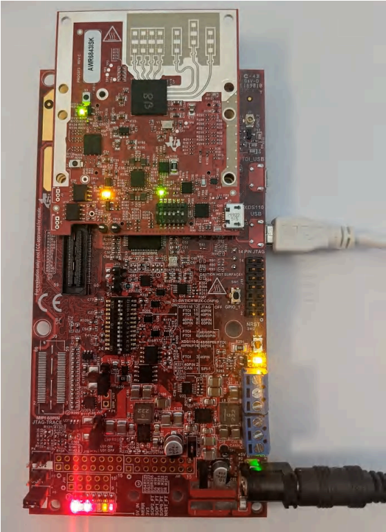
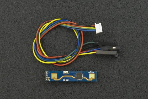
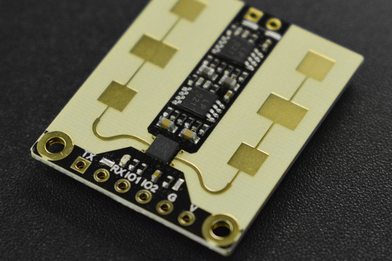
Compare for example some millimeter wave RADAR modules sold for hobbyist project applications vs. a commercial/automotive grade solution from Texas Instruments (TI’s chips are admittedly up in the core mmWave regime at 60-70GHz, so not completely apples to apples). It’s absolutely amazing that anyone can build and sell these complete RADAR modules for under $10 at qty 1, which is less than half the quoted cost of TI’s mmWave radar IC alone (at qty 1,000!), so our goal isn’t to bash these products. For a quick proof-of-concept experiment or a school project they could be fantastic. But, if you were developing a robot for industrial use, and had built the design around this 10 dollar sensor only to find out it doesn’t work well enough, or can’t survive in a high vibration environment, or can’t be configured to resolve housing & radome induced artifacts, or very likely cannot pass required FCC Certification Testing. If you wanted to verify any of those things up front, you’d likely find it difficult, as it’s not clear exactly what IC’s are actually behind this module. And chances are they are Chinese domestic market chips, which may not have any English documentation at all. You can imagine the scope of redesign that would be required to move the design to the professional grade counter part. A switch like this would likely require additional power rails to be added, higher end regulators with better noise characteristics to be specified, improved analog domain filtering, and potentially a more capable MCU to handle the firmware interface. The list goes on, and quickly the prototype is back to being a clean sheet design.
In some cases this can even spell the end of the project. These extremely cheap and easy to get started modules often trick entrepreneurs into thinking a concept is economically viable which simply isn’t, at least yet. In principle, a poorly-performing RADAR sensor or LiDAR scanner can be swapped out for a better one, firmware development work can be done to integrate the more complex interface, the processor can be upgraded to support the higher compute load. But in practice, LiDAR scanners that actually work well, have rigorous performance characterization, and are available from reliable manufacturers can cost upwards of 1,000 dollars. That realization can make a $200 robot concept dead in the water.
Some quick checks to identify these components before you invest in a design built around them:
- Who makes it, and is this a supplier you can rely on for production components?
- You may not be familiar with all the semiconductor and component manufacturers, but, is this a major American or European corporation with significant market share, or a small company registered to a single office suite in Shenzen China?
- How much documentation is there – is the datasheet 3 pages long?
- Is the documentation professional?
- Or, can you find professional documentation for underlying components in addition to hobbyist oriented documentation
- User friendly steam-lined documentation is a great asset – you just want to make sure the long format technical stuff exists for when you eventually need it.
- Can you identify the chips on the board?
- Are they in ACTIVE production lifecycle?
- Are they in-stock, and/or is the lead-time acceptable to your project schedule?
- Can you get in touch with the manufacturer, and actually speak to someone on the phone?
- Can you get a quote for production volume pricing?
- For any type of radio transmitter module, does it carry an FCC certification?
- Your product will typically still have to be certified as a whole, but pre-certified modules make you much more likely to pass without headaches
- Is the performance of the module well specified?
- Assume any unspecified performance metric is bad, impressive specifications tend to make it into the datasheet
- Are there versions of this thing that cost 10x more? How are those companies selling them?
- This is a telltale sign that your module under consideration has a big catch
- Is the quality and pedigree of the module appropriate for the application?
- For example, Chinese designed microcontrollers like the ESP32 family are very popular with hobbyists, but can be a dead end for highly regulated and security critical applications (Medical Devices, Aerospace, Security Sensitive IoT). Designs based on these may never pass necessary compliance tests and security audits.
The Margin-less Design and Cascading Updates
All systems need performance margins to work reliably in the presence of component tolerances, but early stage prototypes generally need a large buffer of performance margin, on all fronts, to account for requirements changes and feature creep without being completely re-designed.
Everyone has heard feature creep is bad, so why should we plan for it? It’s true that uncontrolled, and particularly unneeded feature creep should be avoided at all costs, but it’s also important to accept that the requirements for a product cannot be perfectly understood from the earliest days of the concept. It’s reasonable to expect that some feature changes will become obviously needed after feedback arrives further along (ie, user-testing, compliance testing, manufacturing DFM improvements). So, the earlier a product is in development and specification, the more performance margin we want to see on all fronts. One type of dead-end prototype is a system with no margin on any front, that needs just one more small change.
We like to say that design changes propagate until they find slack (ie, design margin) to absorb them. A simplified example of how a change can “run” might look like this: A prototype may need just one more critical firmware feature to be added, but the microcontroller (MCU) is out of firmware memory or runtime performance. So, the microcontroller is upgraded, but the power regulator supplying it also had no power output margin, and now cannot supply the more powerful MCU. So, the regulator is upgraded, but the PCB layout had no space margin to speak of, and the updated design cannot fit into the existing PCB area. So, the board area is increased slightly, but now the board does not fit into the mechanical enclosure design, and so on.
This creates situations where a design might need one more screen added to it’s GUI, and all of a sudden the mechanical engineer has to update the injection molded plastics. On the face of it this sounds ridiculous, and no one wants to hear this, but it can be the very real cost of pre-mature optimization.
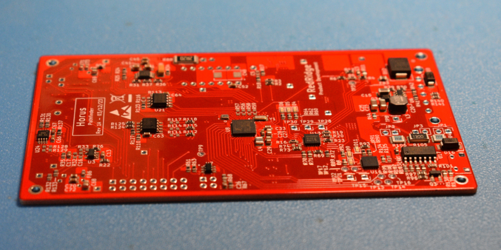
For one example of how to mitigate these issues, see this first-revision PCB designed at RedRidge, which being a first rev has been sized with plenty of physical room left around the board. The board also has generous portions of 0 ohm resistors, DNP options, and test points. As the design matures through subsequent iterations, and the circuits have been validated, many of these convenience and fallback option provisions will be shaved down to meet the target production form factor. This approach to board revision strategy is discussed more in our PCB Layout Services write up.
Some additional tips to avoid the cascading change trap are:
- Design for Microcontroller and FPGA families that offer higher and lower end options in compatible packages
- If you’re still on early stage prototypes, and you’re already needing the highest performance option in your MCU package/family, alarm bells should be going off
- Unless you’re making very high production quantities, know that it’s often cheaper to spec slightly higher performance MCU’s than to pay the engineering costs of toiling away on software optimization. Software optimization often carries diminishing returns and exponentially growing costs
- Avoid specifying commodity components (Mosfets, diodes, etc.) in unique or proprietary component packages unless absolutely neccessary
- If your product is space-constrained, don’t target the final form factor on the very first PCB revision
- Validate circuit designs before you miniaturize them
- Know that debugging electrical issues in highly-aggressive PCB layouts can be difficult or even impossible
- Take extra margin where it’s cheap
- Some capacity comes cheaper than others – power supply margin, for example, can be extremely cheap in low power applications
- If there is a particularly uncertain element of the design, consider how to add a fire line for changes it may face
- Breaking the system element out into a separate PCB, or just budgeting extra PCB space in relevant boards area can make future changes painless
- Evaluate the upstreams of any higher-uncertainty elements
- For example, if you can’t concretely determine the required size of a touchscreen before user testing, the display power supply should be over spec’d, and the mechanical panel should have some room (or a modular interface)
- For battery powered devices, always leave some space margin to accommodate larger battery capacity
- Good low power operation does require firmware optimization, which means the true power draw is often not fully characterized until later in the development cycle – have a plan for how to increase capacity or save cost if it comes in above/below initial projections.
Starting Right
The problems discussed are all best mitigated at the initial inception of a project. If the design is started on the right foot in key component selection, development tooling, and revision planning, it’s easy to keep things on the right track as the design is matured toward production. Conversely, a few major missteps in key component selection can be very costly to back out of late in the design cycle.
If your project is in it’s early days, and the technical road to get from the components and modules you’re currently using to a production-ready version isn’t clear, then best time to figure it out is now. Engineers often make the mistake of assuming it’s not worth delaying actual development work to resolve these planning issues when things are just getting started – but as the saying goes an ounce of prevention is worth a pound of cure.
If your company would like to work with us to get your electronic hardware development started on the right foot, don’t hesitate to get in touch. We’d be happy to discuss your project and see if we would be a good fit.